The Basics of Robotic Deburring for Die Castings

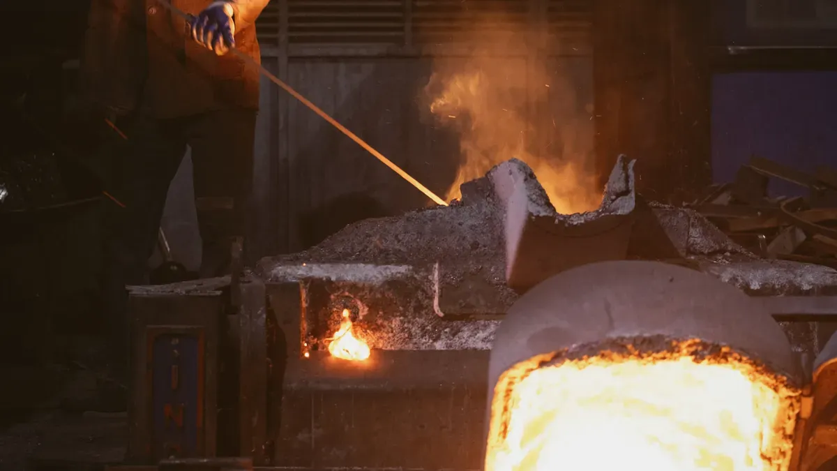
Robotic deburring uses robots with grinding, cutting, or flexible tools to remove flash, parting line burrs, and gate remnants from die castings on their own. This robotic deburring die casting process replaces manual methods that use labor, slow production, and cause uneven quality.
Manual deburring creates bottlenecks. Operators get tired. Quality changes from part to part. Scrap rates go up. Safety incidents happen.
Die casting plants need a better way. Deburring automation gives steady results and higher output. A robot cell does repetitive work without getting tired.
This article explains the burr problem, system parts, setups, tool selection, programming, applications, and realistic ROI metrics for robotic deburring.
Why Manual Deburring Hurts Die Castings
Labor, Rework, and Bottleneck Costs
Big die castings often have heavy flash, parting lines and gate remnants. These features need manual deburring with grinders and files. An operator has to work each part by hand. This step raises labor cost and makes cycle time longer. One large casting can take many minutes to clean.
The hidden costs add up quickly. Rework and scrap go up when operators remove too much material or miss a parting-line burr. Quality changes from part to part. Operators get tired during long shifts. Tiredness slows output and raises mistake rates. The deburring process becomes a bottleneck that starves downstream assembly.
Die casting deburring automation offers a way out. This approach, often called fettling automation, covers all post-die processes. It replaces manual methods with a repeatable machine cycle. The automated vs manual deburring comparison favors automation for large volumes and tight quality targets.
Safety, Training, and Quality Risks
Manual deburring puts operators near sharp edges, flying chips, and vibration. Hand tools cause cuts and strain injuries over time. Safety incidents raise insurance costs and stop production. Plants also have a hard time training new operators. Skill takes months to build. Turnover wears that skill down.
Quality suffers when the workforce changes. A new operator cannot match the feel of an experienced hand. Inconsistent edge quality leads to customer rejects. Deburring automation removes this variability. The robot follows the same path every cycle.
Automation in deburring/ fettling of castings also cuts the die casting deburring automation cost over time. Labor savings, scrap reduction, and steady cycle times drive the payback. Automated deburring gives plants a scalable answer to labor shortages and quality demands.
Inside a Robotic Deburring Cell for Die Castings
A robotic deburring cell for die castings puts together several subsystems. Each part has a clear job. The robot moves the tool or the part. The spindle spins the cutting tool. The tool holder grips that tool. Fixtures hold the casting steady. Sensors watch the contact force. A controller ties everything together.
Robot, Spindle, and Tool Holder Basics
The robot arm makes the motion. Most cells use a six-axis robot. This design reaches complex casting shapes from many angles. The robot carries the deburring tool to the burr. Some layouts flip this setup. The robot holds the casting and moves it against a fixed tool.
The spindle drives the cutting tool at the speed it needs. Spindle power must match the material and the burr size. Aluminum die castings need less spindle power than iron or steel parts. The tool holder links the spindle to the cutter. A rigid holder works well for heavy flash removal. A compliant holder soaks up small position errors.
Tool selection depends on the deburring task. Grinding wheels cut heavy gate remnants. Carbide burrs handle parting-line flash. Files and brushes finish edges. Many cells change tools on their own. A tool changer lets one robotic station run several operations in a row.
Fixtures, Vision, and Force Control
Fixtures locate and clamp the casting. A good fixture holds the part in the same spot every cycle. Positioners turn the part to show each burr to the tool. This setup cuts down robot reach problems. It also makes the cycle time shorter.
Vision systems find the part before deburring starts. A camera scans the casting and reports where it really is. The controller adjusts the path to match. This step matters because castings vary. Die wear, thermal shifts, and mold release all change part dimensions.
Force control keeps the tool pressed against the edge with steady pressure. The controller measures contact force and corrects the path in real time. Compliance adds a spring-like buffer between the tool and the part. A compliant tool holder or an active force sensor soaks up small errors. Without compliance, the tool digs in too deep or lifts away. Both outcomes ruin edge quality.
The design of robotic deburring systems involves trade-off studies. Engineers balance cycle time, cell footprint, tool cost, and part mix. A larger robot costs more but reaches more burr locations. A vision system adds cost but handles casting variation. These choices shape the final performance and price of the cell.
Which Robotic Deburring Cell Fits Your Parts?
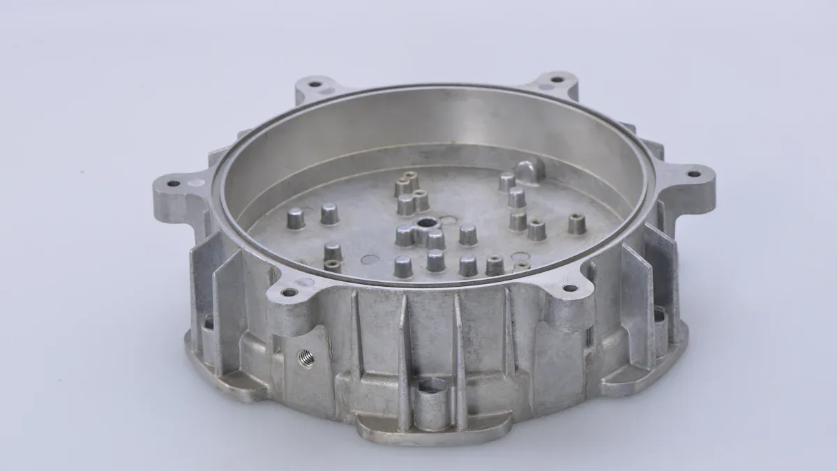
The right layout depends on the part's weight, size, and burr pattern. Two base designs cover most die casting applications. Each design has a clear set of strengths.
Tool-Held vs. Workpiece-Guided Cells
A tool-held cell mounts the deburring tool on the robot wrist. The robot moves the spindle to the casting. This layout handles large, heavy castings well. The casting stays on a fixture. A positioner turns it to show each face. Operators load parts outside the robot's reach. The design keeps the tool small and the robot nimble. It also holds the part steady for tight tolerances.
A workpiece-guided cell reverses the arrangement. The robot grips the casting and moves it against a fixed tool. The tool mounts on a pedestal or a floor stand. This layout suits small and mid-size castings. The robot wrist carries the full part weight plus the gripper. The fixed tool stays simple. Coolant lines and chips stay in place. The cell remains easy to maintain.
Tool-held cells dominate heavy industry. Die casters use them for engine blocks, transmission housings, and motor housings. These parts weigh too much for a robot wrist. Workpiece-guided cells suit brackets, covers, and small housings. A robot cell of this type moves fast. The tool never travels. The robot only swings the part.
Weight often decides the winner. A good rule of thumb: a casting heavier than the robot's rated payload needs a tool-held layout. A lighter casting fits in the gripper. Then compare both options. Consider access too. Tool-held cells reach deep cavities. Workpiece-guided cells struggle with internal features because the part blocks the view. Some factories run both layouts. A tool-held cell removes heavy gates. A workpiece-guided cell finishes light edges.
Matching Tools to Burr Location and Volume
Tool selection follows the burr. Heavy gate remnants need a rigid spindle and a grinding wheel. The wheel removes material fast. Light flash needs a carbide burr at high speed. The burr shaves thin edges without cutting into the base metal. Carbide burrs handle parting-line flash on die castings well.
Location matters as much as volume. Internal bores hide burrs deep inside the casting. Small-diameter, long-reach tools reach those spots. External edges allow larger tools and higher feed rates. A straight file or a sanding disc works on the outside. The robot can push harder against an external edge.
Tool holders add another layer. Heavy roughing demands a rigid holder. Rigid holders transfer spindle torque without flex. Fine finishing uses a compliant holder. The holder absorbs small position errors and keeps pressure even. Some cells carry both tools. An automatic tool changer switches between roughing and finishing in one cycle.
The burr volume sets the spindle power. A low-power spindle handles aluminum castings easily. Iron and steel need a heavier spindle. The burr may cross a long seam. Then choose a wider tool. Wide tools cover more path in less time. Narrow tools reach tight corners but take longer.
Every cell should match tool size to the casting envelope. A large housing with heavy gates calls for a large grinding tool. A small electronics cover needs a light burr. Selecting the wrong deburring tool creates rework. The robot repeats the same mistake every cycle.
Programming and Applying Robotic Deburring Die Casting
Scan-to-Path, Offline Simulation, and Laser Deburring
Programming a robot for die casting deburring starts with path generation. Engineers use offline programming software to make tool paths without stopping production. With CAM path planning, programmers can simulate robot moves and check reach before the cell runs. This approach helps operators with machine tool experience move into robot deburring automation.
Siemens NX offline programming checks robot moves separately from the manufacturing process. This separation allows highly precise path planning for complex shapes. Scan-to-path methods use a laser scanner to capture the actual casting shape. The controller adjusts the path to fit the real part variation.
ZEISS INSPECT software gives guided part programming and automatically checks all robot moves before execution. That ensures a collision-free process. After the best path is generated and verified, the measurement series runs fully automatically.
Laser deburring is another option for delicate features. A laser removes thin flash without touching the base metal. This process works well for finishing aluminum-injected components with tight tolerances.
Applications and ROI for Die Castings
Robotic deburring die casting systems work on engine blocks, transmission housings, and motor housings. These parts have heavy flash and gate remnants. A robot cell removes them with steady cycle times.
The payback case is strong. Reports show 87% less labor, going from 3 operators to 0.5 operators per shift. Scrap goes down by 18%, meaning fewer rejected parts. Throughput goes up 40%, so processing is faster. These gains lower the die casting deburring automation cost over time. Die casting deburring automation has a payback period that most plants measure in months, not years. Deburring turns into a profit center, not a bottleneck.
Plants should match robotic deburring die casting systems to part volume, shape, and quality goals. Heavy parts work well with tool-held cells. Light parts work well with workpiece-guided layouts. High volumes make vision and force control worth the cost.
Use this checklist:
Make sure deburring work is more than manual capacity.
Pick layout by part weight and access.
Choose tools by burr location.
Plan for casting variation.
Start with a pilot cell. Check cycle time and payback first. Die casting deburring automation works best after teams fine-tune paths on real parts. Automated deburring becomes scalable and cost-effective when matched correctly. Deburring automation cuts labor and scrap. A robot cell gives consistent edges every cycle. Engineers should evaluate robotic deburring for their own operations.
FAQ
What are the main parts of a robotic deburring cell?
A robotic deburring cell includes a robot arm, spindle, tool holder, fixture, and controller. Six-axis robots reach complex casting shapes. Spindles drive grinding wheels or carbide burrs. Fixtures hold castings steady. Force control maintains consistent pressure on edges.
Which cell layout works best, tool-held or workpiece-guided?
Heavy castings suit tool-held cells. The robot moves the tool to the part. Light castings suit workpiece-guided cells. The robot moves the part against a fixed tool. Weight and access determine the best choice.
How does force control improve edge quality?
Force control keeps the tool pressed against the casting with steady pressure. The controller measures contact force. It adjusts the robot path in real time. This action prevents the tool from digging too deep or lifting away. Edge quality stays consistent.
What ROI can plants expect from robotic deburring?
Reports show labor drops by 87%. Scrap falls by 18%. Throughput rises by 40%. Payback arrives within months. The deburring process changes from a bottleneck into a profit center.
See Also
How Die Casting Industry Powers Emerging Robotics Market With Parts And Materials
A Complete Step By Step Guide For Die Casting CAD Design
Understanding Functional Testing Within CNC And Die Casting Manufacturing Processes
How To Find The Optimal Die Casting Closing Force For Your Product
How Aluminum Extrusion And Die Casting Manufacturing Processes Actually Work
About Hunan Puka

Established in 2016 and based in Hunan, China, with a liaison point in Berlin, we are a Tier 2 supplier for the automobile industry. We specialize in the production of customized aluminum die-casting parts designed for machines with a closing force ranging from 280 to 1250 tons, with subsequent manufacturing process CNC machining and surface treatment. Our commitment to quality is reflected in our accredited quality management system, certified by ISO9001:2015 and IATF16949:2016 standards.