NADCA Die Casting Tolerances Explained for Engineers

NADCA die casting tolerance is the North American Die Casting Association's published standard. It covers dimensional and geometric variation in die-cast parts. It defines how far a feature can vary from its nominal size.
These tolerances control component fit, functionality, tooling cost, and inspection criteria. Over-tightening them is among the most common and costly design errors. A single needless precision callout can raise tooling costs and slow production.
The next sections show how tolerances are graded, grouped, affected, stated, and checked. Engineers who use the standard as a design tool will avoid costly rework and keep parts manufacturable.
NADCA Die Casting Tolerance Standard and Grades
What the NADCA Standard Covers
The NADCA die casting tolerance framework is built on three things: part dimensions, metal type, and production method. The association publishes its rules in Product Specification Standards for Die Castings (NADCA, USA, 2006). That document defines the normal and precision tolerance grades for high pressure die castings.
Scope is important here. The Normal and Precision grades only apply to high-pressure die castings. NADCA sets separate benchmarks for aluminum high-pressure die casting. The standard also covers dimensional characteristics that are unique to the process. NADCA is recognized around the world for technical standards covering die casting pressure, semi-solid metal (SSM), die steel, and safety.
Each alloy and grade combination has its own numerical limits. The table below shows the base linear tolerance for each metal.
Tolerance Grade | Aluminum | Magnesium | Zinc | Copper |
|---|---|---|---|---|
Normal | ±0.25 mm per 25 mm, plus ±0.025 mm for each additional full 25 mm | N/A | N/A | ±0.36 mm per 25 mm, plus ±0.076 mm for each additional full 25 mm |
Precision | ±0.05 mm per 25 mm, plus ±0.025 mm for each additional full 25 mm | N/A | N/A | ±0.18 mm per 25 mm, plus ±0.05 mm for each additional full 25 mm |
The NADCA standard specifications apply to high pressure die casting tolerances, divided into normal and precision tolerance groups.
Normal vs. Precision Tolerances
NADCA publishes separate tolerance tables for Standard (normal) and Precision tolerances. The two grades serve different purposes, and the cost gap between them is real.
Standard tolerances cover fit, form, and function. Good manufacturing practices achieve them under normal inspection, die life, and production levels. Minor imperfections are allowed. This keeps tooling and piece-part costs low. Most features on most parts belong in this grade.
Precision tolerances allow tighter variation for critical features. A sealing surface, a bearing bore, or a mating interface may justify the tighter grade. The aluminum numbers show the difference. For dimensions within one die half, normal tolerance is ±0.25 mm per 25 mm plus ±0.025 mm for each full 25 mm. Precision tolerance is ±0.05 mm per 25 mm plus the same ±0.025 mm increment.
Projected area changes the allowable variation as well. For aluminum castings up to 65 cm², normal tolerance is ±0.20 mm and precision is ±0.152 mm. At 650–1300 cm², normal tolerance is ±0.81 mm and precision is ±0.61 mm. Larger castings tolerate more variation in both grades.
Engineers should save precision grade for features that really need it. Using it on a whole part raises tooling cost and inspection work without adding any functional value.
Dimensional Tolerances by Feature Type
NADCA sets linear dimension tolerances differently for fixed and moving features. A fixed part is shaped against a die member that stays still. The tooling does not move when metal fills the cavity. The allowed range covers growth, shrinkage, or small flaws in the part. Moving cores have their own tolerance values, shown below. Tolerance grades keep designers, toolmakers, and inspectors on the same page. Everyone reads the same number and agrees whether the dimension must be tight or loose.
Dimensions Within One Die Half and Across the Parting Line
A feature can sit entirely within one die half. The cavity wall forms it without moving tooling. This condition gives the tightest possible results. An aluminum die casting in normal grade has a tolerance of ±0.25 mm per 25 mm, plus ±0.025 mm for each additional full 25 mm. The precision grade allows ±0.05 mm per 25 mm, plus the same ±0.025 mm increase. These two grades have a large gap. For a 100 mm dimension, normal grade allows a wider range than the same dimension in precision grade. Choosing normal grade helps a designer keep tooling and inspection costs low.
Conditions change across the parting line. The dimension now covers two die halves. Each cycle, the die closes, locks, and opens. Mismatch or wear at the parting plane will shift the feature. For this reason, the standard gives looser values for across-parting-line dimensions. Engineers should not use one-die-half tolerance for these features. They should find the parting line on the drawing and assign the right grade per side.
Dimensions Toward Moving Cores
Moving cores make holes, undercuts, and side features. A core slides in, forms the shape, then retracts. The fit between the core and the die body shifts as the tool wears. Thermal expansion and core shift also change the final dimension. So the tolerance must treat the moving member on its own.
The table below shows aluminum tolerances for a moving core surface.
Tolerance Class | Surface Condition Involving Moving Core | Tolerance Value |
|---|---|---|
Normal | Both surfaces in the same die half, the other surface is a moving core surface | 0.20 mm per 75 mm + 0.038 mm per each additional 25 mm |
Normal | Surfaces across the parting line or the other surface parting surface, tolerance towards a moving core surface | 0.28 mm per 75 mm + 0.076 mm per each additional 25 mm |
Precision | Both surfaces in the same die half, the other surface is a moving core surface | 0.13 mm per 75 mm + 0.025 mm per each additional 25 mm |
Precision | Surfaces across the parting line or the other surface parting surface, tolerance towards a moving core surface | 0.20 mm per 75 mm + 0.05 mm per each additional 25 mm |
These numbers are not the same as fixed-cavity values. Put a normal moving-core dimension next to a normal fixed dimension. The moving-core allowance is often wider. That wider value is not a mistake. It allows for real tool movement. The die caster must fit the core, remove it, and repeat the cycle thousands of times.
Engineers should label moving-core features clearly. The drawing should separate fixed dimensions and core-controlled dimensions. A single global tolerance will not work here. If a part needs a precise hole or slot, use the precision row only for that local spot. Leave the rest of the part in normal grade. This method controls cost without losing function.
Geometric Tolerances and Tolerance Drivers
Flatness, Parallelism, and Other Form Tolerances
Linear dimensions do not tell the whole story. A casting can meet tight linear tolerances and still have a lot of flatness deviation. ISO 8062-3 splits linear dimensional tolerances (DCTG) from geometric casting tolerances (GCT). GCT covers form and orientation: straightness, flatness, roundness, parallelism, perpendicularity, symmetry, and concentricity. NADCA puts flatness, parallelism, and perpendicularity into one angular tolerance group. This group is split into Normal and Precision levels.
Flatness values scale with the raw casting basic dimension. NADCA allows 0.20 mm for the first 75 mm plus 0.08 mm per additional 25 mm. ISO 8062-3 GCTG 3 permits 0.18 mm at dimensions up to 10 mm and 0.90 mm at 300–1000 mm. The chart below compares these values across dimension ranges.
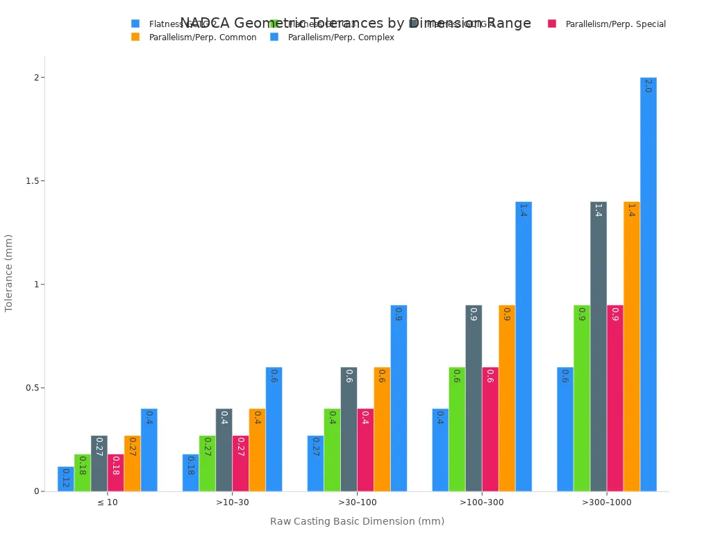
Angular tolerance depends on die configuration. Surfaces in the same die half get the tightest values. NADCA normal grade allows 0.13 mm per 75 mm plus 0.025 mm per additional 25 mm for this case. Surfaces across the parting line allow 0.20 mm per 75 mm plus 0.038 mm per additional 25 mm. Precision grade cuts these values by about half.
Factors That Affect Achievable Values
Several variables drive the final numbers. Raw casting basic dimension is the main driver. It is calculated from the largest dimension, such as corner-to-corner for rectangular objects. Casting complexity shifts tolerances coarser. Moving die components need more allowance than fixed surfaces. Projected area drives parting line shift. This shift ranges from ±0.102 mm below 325 cm² to ±0.635 mm at 5160–7740 cm².
Alloy and process conditions matter too. Aluminum shrinkage runs about 1.3% nominal, but measured values reach 2.4%–2.84% for A356. Pouring temperature, cooling rate, and tooling variables all influence the result. Alloy type also sets dimensional grades: zinc falls in DCTG 3–6, copper in DCTG 6–8. Engineers should confirm achievable values with the die caster before finalizing any NADCA die casting tolerance callout.
Specifying NADCA Die Casting Tolerances on Drawings
If a drawing does not show tolerance grades, the toolmaker must guess. That guesswork causes rework. A better way is to use the NADCA die casting tolerance. Choose normal grade by default. Use precision grade only for sealing surfaces, bearing bores, or mating interfaces that truly need it.
Calling Out Grades Correctly
Start by choosing a tolerance class, not a blanket value. Do not assume that a single tight value like ±0.1 mm applies to every feature. The die casting process usually gets around ±0.1 mm. Tighter allowances belong only on features that truly require them. A global callout of ±0.1 mm forces every surface into that standard, even cosmetic areas that never need it.
Instead, give each feature its own grade. A dimension inside one die half can safely use normal grade. A dimension across the parting line needs a looser value. Moving-core dimensions need their own allowance. Drawings should mark the grade for each feature, so inspectors and the die caster read the same requirement. Check the NADCA section for each feature type.
Avoiding Over-Specification and Cost Creep
Tight tolerances often show up on drawings for the wrong reasons. The first question should be: Does the part's function truly need this variation? Engineers sometimes keep tolerances from an old design without rechecking. Machining tolerances get confused with casting tolerances. Both mistakes raise tooling cost and inspection time.
Ask the contract manufacturer to review the drawing. Die casters can flag too-tight tolerances and suggest practical ranges. Confirm wall thickness, draft angles, alloy and temper, and surface finish needs. Then final tolerances match what the process actually delivers.
Do not loosen tolerances too much. Use quality checks and tolerance analysis to find where tight limits matter. Machine critical interfaces — mounting surfaces, mating bores, threaded holes — to meet assembly tolerances. Leave non-critical features at as-cast tolerance. This approach keeps NADCA die casting tolerance precise where it matters, loose where it doesn't, and cost under control.
Measuring, Validating, and Misinterpretations
Inspection Methods and Validation Practices
Checking a part starts with the drawing. Inspectors look at the tolerance grade marked on each feature. Then they measure the part with tools that match that grade. Calipers and micrometers work for general dimensions. Coordinate measuring machines (CMMs) handle complex shapes and tight precision features. Optical comparators and vision systems are good for small features and high-volume checks.
Validation does not stop with one good part. The die caster should run a capability study on a production sample. This study shows whether the process holds the specified NADCA die casting tolerance over many cycles. Engineers should ask for this data before approving a drawing. One conforming sample proves very little about long-run capability.
Misconceptions Engineers Should Drop
Several wrong beliefs about tolerance grades cause trouble on the shop floor.
A specified tolerance grade is not automatically guaranteed. Grades describe what is achievable under proper process conditions. Standards note these grades are typically attainable only for long production runs or mature processes. Short-run or less-developed processes may need coarser grades, since meeting a grade depends on part geometry, tooling quality, and process maturity.
Wall thickness and linear dimensions cannot share the same tolerance grade. Wall thickness depends on the relative positioning of core and cavity. Applying the same grade to both creates an unachievable specification. Wall thickness must always be treated as one grade coarser than linear dimensions.
Die casting tolerance grades do not apply to all casting processes. Each process occupies a distinct tolerance range. NADCA Normal and Precision grades apply only to high-pressure die casting, not to sand or gravity casting. Specifying tight grades on a sand-cast part without machining is not achievable as-cast.
Precision tolerance grades do not come without extra burden. Precision grades carry additional cost and require stricter process-control requirements.
Engineers who drop these misconceptions avoid unachievable callouts and unnecessary cost.
NADCA die casting tolerance shows what can really be made, not what you hope for. Normal and precision grades are used for different jobs. The rules for size and shape change with each feature type. Alloy, part shape, and tooling decide the true limits.
Pick the loosest tolerance that still meets fit, form, and function. Save precision grade for critical features only. Check with the die caster early, before drawings are locked in.
Use the NADCA standard as a design tool. Engineers who plan tolerances during design avoid rework, control cost, and keep parts easy to make.
FAQ
Which tolerance grade should I use by default?
Start with normal grade. It covers fit, form, and function when manufacturing follows good practices. It also keeps tooling and piece-part costs low. Save precision grade for sealing surfaces, bearing bores, or mating interfaces that truly need tighter variation. Most features on most parts work fine in the normal grade.
Does specifying precision grade guarantee the part will meet it?
No. Grades describe what is achievable under the right process conditions. NADCA notes these grades are usually attainable only for long production runs or mature processes. Short-run or less-developed processes may need coarser grades. Meeting a grade depends on part geometry, tooling quality, and process maturity.
Can wall thickness use the same tolerance grade as linear dimensions?
No. Wall thickness depends on how the core and cavity line up with each other. Using the same grade for both creates a spec that cannot be met. Wall thickness must always be treated as one grade coarser than linear dimensions.
Do NADCA Normal and Precision grades apply to sand or gravity casting?
No. Each casting process has its own distinct tolerance range. NADCA Normal and Precision grades apply only to high-pressure die casting. Tight grades on a sand-cast part without machining cannot be achieved as-cast.
How do I confirm the die caster can hold my specified tolerance?
Ask for a capability study on a production sample. This study shows whether the process holds the specified tolerance over many cycles. One conforming sample proves very little about long-run capability. Confirm achievable values with the die caster before you finalize any callout.
See Also
The Essential Guide To Casting Shrinkage And Machining Allowance
Functional Testing Explained For CNC And Die Casting Processes
Top Advantages Of CAE Analysis For Die Casting Design
Your Practical Guide To Die Casting CAD Design Steps
A Supplier's Guide To CBAM And Sustainable Casting Practices
About Hunan Puka

Established in 2016 and based in Hunan, China, with a liaison point in Berlin, we are a Tier 2 supplier for the automobile industry. We specialize in the production of customized aluminum die-casting parts designed for machines with a closing force ranging from 280 to 1250 tons, with subsequent manufacturing process CNC machining and surface treatment. Our commitment to quality is reflected in our accredited quality management system, certified by ISO9001:2015 and IATF16949:2016 standards.