Machining a Die-Cast Aluminum Hydraulic Valve Body

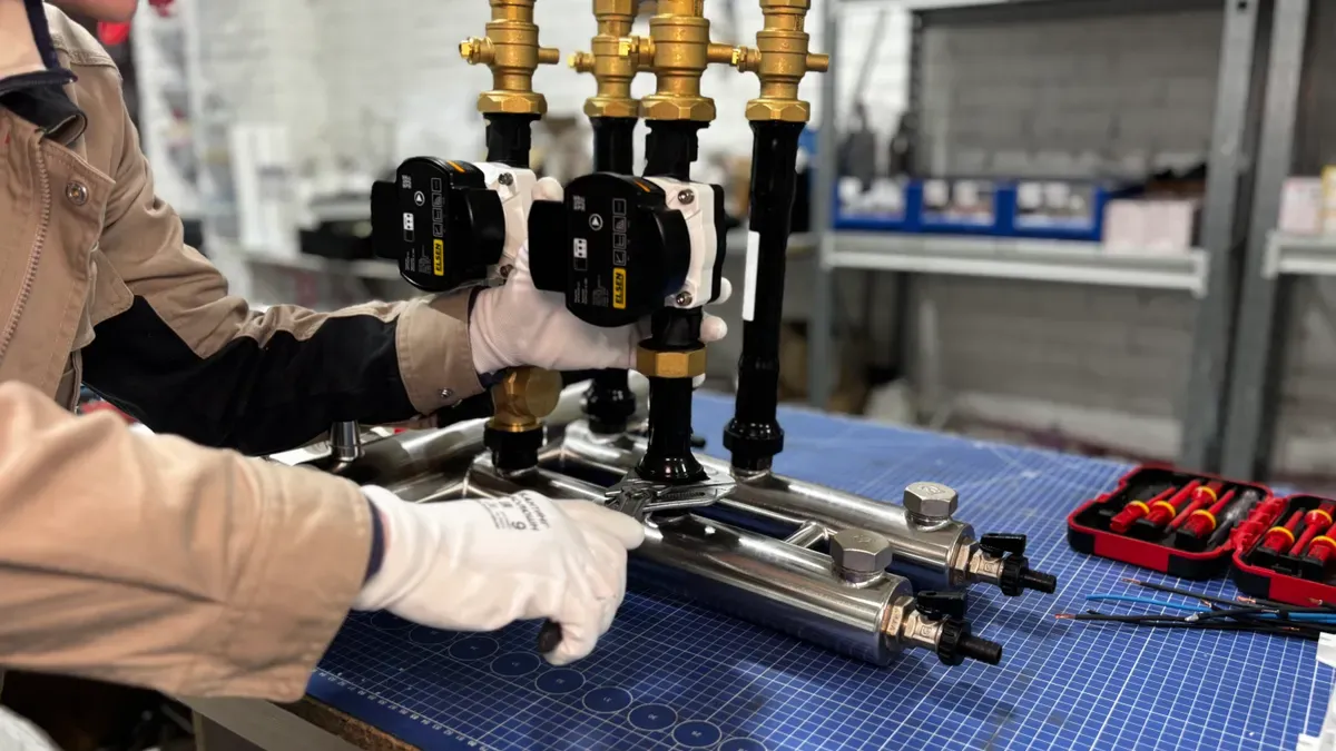
Die-cast aluminum hydraulic valve bodies boost performance in construction machinery and industrial hydraulic systems. The valve body guides fluid, holds internal parts, and keeps pressure steady across every circuit. Porosity at oil passage intersections creates a serious problem. Leaks and flow limits can result. Valve bores and seal grooves need precise machining, because cast surfaces cannot hold the tight tolerances these features require. Deburring oil passage intersections also proves essential for clean fluid flow. Engineers, machinists, and technical buyers all gain from understanding the full production path. Design, die-casting, CNC machining, deburring, cleaning, inspection, and finishing each shape the final part. Careful control at every stage separates reliable valve bodies from problem parts.
Hydraulic Valve Body Basics
A hydraulic valve body is the main part of every control circuit. It sends pressurized fluid where it needs to go, holds moving parts, and keeps system pressure steady. These jobs require strong material and careful machining. Construction machinery and industrial hydraulics depend on these parts for safe, repeatable work.
Core Functions in Hydraulic Systems
Valve bodies do three important jobs in a hydraulic system.
Directing Fluid Flow
The body has a network of cast passages and drilled holes. These channels carry fluid to actuators, motors, and working ports. Directional spools slide inside precision bores. Their movement opens or blocks circuit paths. Clean, smooth passage walls cut down on turbulence and pressure loss. The right flow direction makes machine functions work as commanded.
Housing Internal Components
Every valve body must hold spools, poppets, springs, and seals. Machined bores keep these parts in exact alignment. Seal grooves hold O-rings firmly in place. The housing also shields internal parts from outside contaminants. Strong walls resist bending under mechanical and hydraulic loads.
Maintaining Pressure Integrity
Hydraulic systems run at high pressures. The valve body must hold this force without leaking. Wall thickness, sound material, and flat sealing surfaces all help with integrity. Porosity in die castings can make hidden leak paths. Machining exposes defects below the surface, and pressure testing checks soundness. A strong structure prevents downtime and safety hazards.
Why Material Choice Matters
Die-cast aluminum has become the standard material for hydraulic valve bodies. Its properties match performance needs directly.
Strength-to-Weight Ratio
Aluminum alloys give high structural strength at low mass. This ratio matters a lot in mobile equipment. Lighter valve bodies cut down overall machine weight. Lower weight improves fuel efficiency and allows larger payloads. Designers can also add shaping for strength without adding much weight.
Corrosion Resistance
Aluminum forms a protective oxide layer that resists corrosion. This layer stands up to moisture, humidity, and many hydraulic fluids. Construction environments expose parts to rain and mud. Corrosion resistance keeps valve bodies working reliably outdoors. Surface treatments can further improve long-term durability.
Thermal Management
Heat is a constant challenge in hydraulic systems. Aluminum conducts heat far better than steel. This thermal conductivity helps dissipate heat from working fluid. Cooler operation maintains consistent oil viscosity and component clearances. It also prolongs seal life and prevents thermal damage to precision surfaces.
Common Valve Body Types
Engineers choose among several construction styles based on application needs.
Monoblock vs. Sectional
Monoblock bodies are cast as a single piece. This design yields a compact valve assembly with fewer potential leak points. Sectional bodies stack multiple individual sections with tie bolts. They permit custom valve configurations and easier replacement of one section. Monoblock suits high-volume, fixed-function machines. Sectional suits lower-volume or adjustable systems.
Cartridge vs. Manifold
Cartridge-style bodies accept threaded cartridges. Operators can remove and replace a cartridge without disassembling the entire valve. This simplifies maintenance. Manifold bodies integrate multiple valve functions into one machined block. Internal passages replace external hoses and fittings. This arrangement reduces plumbing weight and leak paths while increasing circuit density.
Design for Die-Cast Aluminum
Die-cast design begins by thinking about the steps that come later. The casting gives you a rough shape. CNC machining turns that shape into a working valve body. Before metal goes into the die, engineers plan how much material to remove, how the part will release, and how to keep it strong.
Wall Thickness and Structure
Minimum Wall Thickness Guidelines
Die-casting only works within a certain wall thickness range. Casters cannot fill very thin sections in a reliable way. Thick walls cause shrinkage porosity that makes passages weak. A hydraulic valve body keeps wall thickness as even as possible. Even sections cool at the same rate and cut down on internal voids. Designers stay away from sudden changes between thick and thin areas. When a change is needed, they add smooth transitions. This keeps pressure integrity high and makes the part easier to cast.
Ribbing and Reinforcement
Ribs add stiffness without needing thicker walls. A ribbed structure resists bending when bolts clamp valve sections together. Reinforcement should follow the paths where loads travel. Mounting bosses and flanges often need extra support. Ribs also spread stress around machined cavities. Simple rib layouts work best; complex shapes trap die material and make ejection harder. A well-placed rib improves both casting quality and final part strength.
Draft Angles and Parting Lines
Recommended Draft Angles
Every surface that touches the die needs a draft angle. Draft lets the solid part release without dragging. Not enough draft raises ejection forces and tears surfaces. External walls need only a small taper, while deep internal bores need a larger one. Die-cast valve bodies include draft on as-cast surfaces. Critical valve bores get machined later, so their cast form needs only enough draft for ejection.
Impact on Ejection and Finish
Proper draft lowers ejection effort and protects surface finish. Steeper draft gives cleaner as-cast surfaces. Parting lines, where die halves meet, create thin flash. Removing flash adds time and can leave marks. Designers place parting lines away from sealing surfaces when they can. This placement makes trimming simpler and avoids damage to valve bore mouths.
Machining Allowances and Tolerances
Stock Allowance for Critical Surfaces
Valve bores and seal grooves cannot work as-cast. Cast surfaces are too rough and out-of-tolerance for spools and O-rings. The design leaves extra stock on these features. The machining process removes that stock to reach final size, roundness, and finish. The allowance also cleans up surface porosity. Too little stock exposes flaws near the skin. Too much stock creates deep cuts and extra cycle time. Designers balance both constraints.
Tolerance Stack-Up Considerations
This machining depends on reliable reference points. Casting tolerances vary more than machining tolerances. Without a clear datum, misalignment builds up. Tolerances stack up across multiple machined faces. The solution involves machining one master datum first and carrying all locations from that datum. Oil passage intersections deserve special attention. These crossing points are prone to porosity because metal flow and solidification collide there. The design should position intersections in zones that permit inspection and, if needed, plugging or sealing after machining. Planning for this possibility avoids costly rejections.
Die-Casting Aluminum Alloys and Process
Choosing the Right Alloy
A380 for High-Volume Production
A380 is the most common die-casting aluminum alloy. It gives a great mix of strength, castability, and cost. This alloy flows well into thin walls and complex shapes. It also resists hot cracking when it solidifies. These traits make it good for high-volume runs of hydraulic valve bodies. A380 machines easily, so secondary operations stay efficient. The alloy handles the pressures and temperatures of construction machinery and industrial hydraulics.
6061 for Prototypes and Low Volume
6061 is a wrought aluminum alloy, not a die-casting alloy. Shops use it for prototypes and low-volume runs. They machine 6061 from solid billet or plate. This approach avoids the cost of a die for early testing. Engineers can check valve bore sizes, seal groove locations, and flow paths before committing to production tooling. The material gives good strength and corrosion resistance. It also welds and machines well. Once the design proves out, production shifts to a die-cast alloy like A380.
A383, ADC12, and B390
A383 changes A380 for better die filling and less porosity. It works well for intricate valve bodies with thin walls. ADC12 is the Japanese equivalent of A383 and sees wide use in Asian production. B390 is a hypereutectic alloy with high silicon content. It provides excellent wear resistance for valve bores that see sliding contact. Each alloy serves a specific need. The choice depends on wall thickness, wear requirements, and production volume.
Advantages of Die-Cast Aluminum
Weight Reduction
Aluminum weighs about one-third as much as steel or cast iron. This difference matters greatly in mobile equipment. A lighter valve body reduces overall machine mass. Lower mass improves fuel economy and allows larger payloads. Die-casting also permits thin, stiff walls that further cut weight. The weight savings add up across every hydraulic circuit on a machine.
Thermal Conductivity
Aluminum conducts heat far better than steel. This property helps hydraulic systems run cooler. Heat from the working fluid moves through the valve body and dissipates into the air. Cooler fluid maintains stable viscosity and protects seals. It also reduces wear on spools and bores. Die-cast aluminum valve bodies therefore support longer service life in demanding applications.
Cost Efficiency at Scale
Die-casting delivers strong cost advantages at high volumes. One die can produce thousands of parts with minimal labor. Cycle times are short, and material waste is low. Near-net shapes reduce machining time and scrap. The tooling investment pays back quickly when production runs are large. For construction machinery and industrial hydraulics, this efficiency keeps unit costs competitive.
Die-Casting Steps and Machine Sizing
Mold Design and Preparation
Mold design starts with the part geometry and alloy choice. Engineers plan the parting line, draft angles, and gate locations. They also design cooling channels to control solidification. The die must fill completely before the metal freezes. Proper venting lets trapped air escape. A well-designed die reduces porosity and extends tool life. Preparation includes polishing cavity surfaces and checking alignment.
Injection, Cooling, and Ejection
The die-casting machine injects molten aluminum into the die at high speed and pressure. The metal fills the cavity and takes the shape of the mold. Cooling channels then remove heat until the part solidifies. Ejection pins push the finished casting out of the die. The part then goes to trimming, where operators remove flash and runners. Porosity at oil passage intersections is a common die-casting defect. Machining must address this issue by removing flawed material and exposing sound metal.
500–1250T Machines for Mid-Sized Valve Blocks and Pump Covers
Die-casting machines are rated by clamping force in tons. Machines in the 500–1250T range suit mid-sized valve blocks and pump covers. These machines provide enough force to hold the die closed against injection pressure. They also handle the projected area of typical hydraulic components. Larger machines cost more to run, so matching tonnage to part size controls cost. A 500–1250T machine balances capability and efficiency for many valve body designs.
CNC Machining Operations
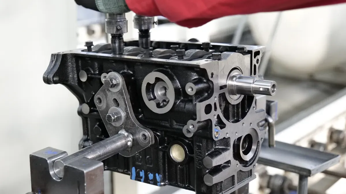
CNC machining changes a rough die-cast shape into a working hydraulic valve body. The casting gives the basic form. The machine tool cuts every critical surface to the final size, roundness, and finish. Valve bores and seal grooves must be machined, not used as-cast, to make sure they don't leak. Cast surfaces cannot hold the tight tolerances that spools and O-rings need. This stage also removes porosity near the surface and creates flat sealing faces that keep pressure inside the circuit.
Pretreatment and Fixturing
Deburring Castings Before Machining
Raw castings come with flash, parting line fins, and gate marks. These features get in the way of workholding and can damage cutting tools. Operators remove them before the part goes into the CNC machine. A clean casting sits flat on the fixture and locates against consistent surfaces. This pretreatment step protects both the part and the machine. It also lowers the risk of loose material breaking free during cutting.
Workholding for Complex Geometries
Hydraulic valve bodies have irregular shapes with many bosses, ports, and angled faces. Standard vises cannot hold them securely. Shops build custom fixtures that match the casting geometry. These fixtures use locating pins, clamps, and support blocks to lock the part in place. A rigid setup stops vibration during cutting. Vibration ruins surface finish and shortens tool life. Good workholding also lets you reach multiple faces in one setup, which improves accuracy and cuts cycle time.
Primary Machining Steps
Face Milling and Pocket Milling
Face milling creates flat mounting surfaces and sealing faces. The cutter passes over the casting and removes stock in one or more passes. Flatness matters most on surfaces that mate with other components. Pocket milling cuts recesses for cartridges, covers, and internal passages. The tool follows a controlled path to remove material without gouging the walls. Both operations need sharp tools and stable cutting parameters. Dull tools push the material instead of cutting it, which raises heat and damages the surface.
Drilling and Tapping
Drilling creates the holes for mounting bolts, port connections, and oil passages. The drill enters the casting at a precise location and angle. Tapping cuts threads into those holes. Thread quality determines how well fittings seal and how much torque the joint can take. A worn tap produces rough threads that leak under pressure. Operators check thread depth and pitch with gauges during the run. Consistent drilling and tapping keep assembly smooth and reliable.
Boring and Reaming for Precision Holes
Boring makes a hole larger to an exact diameter and improves roundness. Reaming finishes the hole to a fine surface and tight tolerance. Valve bores need both operations. A spool must slide inside its bore without binding or leaking. The bore diameter, straightness, and finish all affect performance. Reaming removes the last small amount of material and leaves a smooth wall. This step separates a working valve body from a rejected one.
Machining the Valve Bores and Seal Grooves
Achieving Flat Sealing Surfaces
Seal grooves hold O-rings and other sealing elements. The groove floor and walls must be flat and smooth. Any roughness or waviness lets fluid escape under pressure. The cutting tool must run true and stay sharp. Operators measure groove width and depth against the print. A groove that runs too deep loses its squeeze on the seal. A groove that runs too shallow prevents the seal from seating. Both errors cause leaks. Precision machining here protects the entire hydraulic circuit.
Intersection Deburring for Fluid Flow
Oil passages cross each other inside the valve body. The machining process creates burrs at these intersections. A burr restricts flow and can break loose later. Loose metal travels through the system and damages pumps, valves, and actuators. Deburring at oil passage intersections is critical to prevent flow restriction and contamination. Shops use special tools to reach inside the passages and cut away the burrs. Some operations use abrasive flow or thermal methods. The goal is a clean, open intersection that lets fluid move freely.
Deburring, Cleaning, and Cleanliness
Deburring and cleaning turn a machined casting into a hydraulic part you can trust. Cutting tools leave sharp edges and loose metal behind. These flaws block fluid flow and dirty the system. Every oil passage intersection must have no burrs at all so fluid can flow right. A clean valve body keeps pumps, valves, and actuators safe from harm.
Deburring Methods After Machining
Manual and Automated Deburring
Manual deburring uses hand tools to reach edges and corners. This works for low volumes and simple shapes. Automated deburring runs on a CNC machine with standard tool shanks. NamPower® brushes handle flat surfaces and edges. Flex-Hone® tools deburr bores and cross holes. These tools load through normal tool changes. This method allows in-process deburring with typical time savings of 30–60 seconds per workpiece. Automated deburring gives the same results every time and cuts labor cost.
Abrasive choice depends on the base material. The table below helps with this choice.
Abrasive Type | Best Suited For |
|---|---|
SC (Silicon Carbide) | Steel and cast iron; about 80% of applications |
AO (Aluminum Oxide) | Aluminum, copper, and brass; softer materials |
BC (Boron Carbide) | Hardened steels and ceramic coatings |
D (Diamond) | Nikasil, hard chrome, and extremely hard surfaces |
For aluminum valve bodies, AO abrasives work best. They cut the softer material without digging into the surface.
Intersection Deburring for Oil Passages
Oil passages cross inside the valve body. These crossings create burrs that block flow. A three-step process removes them well.
Run a Flex-Hone® through the main bore to deburr the intersection edges.
Insert a miniature brush into the cross hole to remove leftover burrs.
Finish by blowing out debris with compressed air.
Flex-Hone® is a flexible honing tool with abrasive globes on nylon filaments. It makes a uniform cross-hatch finish in bores. It removes burrs and makes the surface better. The tool works on cylinder finishing, valve guides, hydraulic bores, and cross-hole deburring. Flex-Hone® can run on a CNC machine and is preferred for repeatable production results. The process needs programming of RPM, stroke feed rate, and dwell time. A floating holder is suggested to make up for alignment tolerances. The cylindrical shank fits standard collet chucks.
Brush size matters for good deburring. The brush should be 5–15% larger than the bore diameter. For example, a 30 mm bore would use a 32–34 mm brush. If the brush is too small, it will not touch the surface. If the brush is too large, it may get stuck. For cleaning, use the upper range of about 15%. For deburring, use a more careful 5–10%.
Shops pick between thermal deburring and brush tools based on volume and shape.
Method | Advantages | Limitations | Best Use Case |
|---|---|---|---|
Thermal deburring (TEM) | Deburrs all areas at once, even hard-to-reach spots | High investment, no edge rounding, economical only for series production | Very high volumes with very complex shapes |
Brush tools (Flex-Hone®, NamPower®, miniature brushes) | More flexible, more affordable, can also improve surface finish | May need tool changes and process programming | Complex crossing passages and lower-to-medium production volumes |
Brush type also changes the result. Wire brushes (steel, stainless steel, brass) remove rust, scale, slag, and old coatings. Nylon brushes (with or without abrasive grain) work gently for deburring, finishing, and sensitive surfaces. A simple rule applies: use nylon if the surface must not be changed; use wire if you want to remove material.
Cleaning Principles for Hydraulic Bodies
Removing Chips, Burrs, and Contaminants
Cleaning removes chips, burrs, and other dirt from inside and outside the valve body. Machining makes metal chips that get stuck in passages and blind holes. These bits cause wear and block flow. The cleaning process uses fluid flushing, air blasting, and sometimes ultrasonic baths. Each step targets different dirt sizes and locations. The goal is a body with no loose material before assembly.
Why Cleanliness Matters for Fluid Control
Cleanliness directly affects fluid control. A single chip can jam a spool or block a small hole. This failure stops the machine or causes unsafe movement. Dirt also speeds up wear on pumps and actuators. A clean valve body keeps pressure and flow steady. It protects the whole hydraulic circuit from damage.
Cleanliness Verification by Principle
Visual and Functional Checks
Verification confirms that cleaning worked. Visual checks look for chips, burrs, and debris on inside surfaces. Functional checks confirm that fluid passes through passages without blockage. A flow test measures pressure drop across the valve body. High pressure drop means a blockage or a burr still there. These checks catch problems before the part reaches assembly.
Avoiding Fabricated Standards
Cleanliness verification follows principles, not made-up standards. Shops set their own acceptance rules based on what the application needs. They inspect critical passages and sealing surfaces with borescopy or bright light. They test flow and pressure to confirm function. This practical approach ensures reliable performance without citing random grades. The focus stays on real-world function, not paperwork.
Quality Control and Inspection
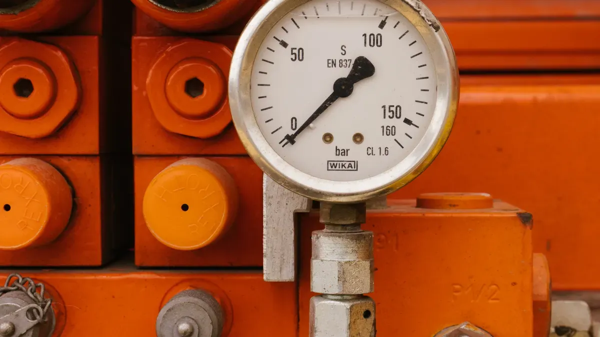
Quality control keeps the money spent on machining safe. Every valve body has to meet exact specs before it leaves the shop. Seal surfaces and valve bores need the closest watch. These features control leaks and how the spool moves.
In-Process Inspection
In-process inspection catches mistakes before they turn into scrap. Operators measure parts while the CNC program is still running. CMMs and surface gauges give feedback right away. Machinists can fix tools before bad parts pile up.
Dimensional Checks with CMMs
Coordinate measuring machines check the dimensions that matter most. They measure bore diameter, roundness, and position at several points. Seal groove width and depth also get checked by CMM. The machine compares each reading to the engineering tolerance.
Measuring early is important. A valve body with a bad bore wastes valuable cycle time. Finding the problem after machining means rework or scrap. In-process CMM checks lower that risk. Operators check the first part from every setup.
Surface Finish Measurement
Surface finish gauges read roughness on machined faces. A stylus runs across the surface and records the tiny profile. Valve bores need a smooth finish so the spool can travel. Seal grooves need a smooth finish so the O-ring can seat.
Roughness readings help decide when to replace tools. A dull cutter leaves a rougher surface. The gauge spots that change before the eye can. Steady finish protects sealing performance over thousands of cycles.
Leak and Pressure Testing
No leak test means no proof of pressure integrity. Every casting can hide internal voids. Porosity at oil passage intersections often stays invisible. Pressure testing brings these defects to light.
Air Decay and Hydrostatic Testing
Air decay testing fills the body with compressed air. The operator seals all ports and measures pressure drop over time. A slow pressure drop points to an internal leak path. The test is fast and clean.
Hydrostatic testing uses water or hydraulic fluid. It fills the body and pushes it far above working pressure. This proves the body can hold force. Cracks and open porosity cause leaks you can see. Parts that fail either test must be rejected.
Flow and Pressure Drop Verification
Flow verification proves the passages really work. A test manifold connects to the valve ports. Fluid flows through the body at a rated flow rate. Pressure sensors measure the loss across each circuit.
A high-pressure drop means a restriction is still there. Chips, burrs, or flash could block the passage. A clean body shows smooth, predictable pressure loss. Flow tests also confirm the spool moves the right way.
Final Inspection and Traceability
Final inspection gives the customer confidence. It pairs a visual review with a full dimensional record. Traceability links every part to its production history.
Visual and Dimensional Final Checks
Inspectors look over every sealing surface by eye. They check for nicks, scratches, and leftover flash. A small scratch on a valve bore can create a leak path. Dimensional checks repeat the CMM work one last time.
Final checks cover ports, threads, and mounting faces. Inspectors confirm thread depth and port position. They also check flatness on mating faces. A flat face stops leaks at bolted joints.
Certificates of Conformance
Every shipment comes with a certificate of conformance. This document lists the tests and their results. It confirms the parts meet drawing requirements. A certificate also includes lot numbers and test dates.
Traceability records show the casting heat and machining lot. If a problem shows up in the field, engineers can trace it back. They can inspect the same lot for similar issues. This record creates accountability.
Surface Finishing and Applications
Aluminum valve blocks often get anodic oxidation as a finish. This coating keeps parts safe before use and gets them ready for harsh places.
Anodizing and Other Finishes
Type II vs. Type III Anodizing
Type II anodizing makes an even oxide layer. It gives corrosion resistance and a good base for paint. Most industrial hydraulic fluids do not break down this film.
Type III anodizing, or hard anodizing, forms a thicker, harder coating. It fights wear on sliding parts and threaded areas. The size changes more, so machinists cover critical bores or machine them after coating.
Chromate Conversion and Powder Coating
Chromate conversion puts on a thin chemical film. This finish shields aluminum without changing part sizes. It works where tight tolerances must stay exact.
Powder coating adds a heavy outer layer. It stands up to scratches, chemicals, and weather. Shops often coat only the outside and cover threads, bores, and seal grooves.
Key Industries and Use Cases
Construction Machinery and Industrial Hydraulics
Construction machinery and industrial hydraulics use cast control blocks as main parts. Aerial platforms, forklifts, vehicle tailgates, and dock levelers depend on these parts. The blocks make fluid paths shorter, cut pressure loss, and make installation simpler.
Hydraulic equipment runs at high pressure and often moves on vehicles. Valve blocks must be stronger and more reliable than fixed options. Cast control blocks join valves and connections to save space and lower leak risk. Flow-optimized internal channels reduce resistance and boost energy efficiency.
Automotive and Aerospace
Automotive and aerospace use compact control blocks for exact fluid control. Engineers match flow rates, valve load capacity, and valve positioning during design.
Material choice follows pressure, temperature, and media compatibility. Surface finish also depends on the working environment and fluid type. A tough coating makes service life longer.
Benefits of Die-Cast Aluminum Valve Bodies
Weight and Efficiency Gains
Die-cast aluminum cuts total machine weight. Internal channels remove external hoses and fittings. Fewer connections mean fewer leaks and lower pressure drop.
The casting process makes complex internal shapes. These shapes support smooth flow and compact packaging. A lighter, smaller valve block improves efficiency and makes maintenance easier.
High-Volume Production Savings
Die casting pays off at scale. One die makes thousands of bodies with little labor. Near-net shapes cut machining time and scrap.
Tooling costs spread over a large production run. Construction machinery, engineering machinery, machine tool building, textile machinery, and mini hydraulic power units all gain. Die-cast aluminum gives steady quality at a lower unit cost.
Making a reliable die-cast aluminum hydraulic valve body takes a series of careful steps. Design picks wall thickness, draft angles, and machining allowance. Die-casting makes the rough shape in alloys such as A380. Because cast surfaces cannot seal or guide a spool, CNC machining then cuts valve bores and seal grooves to tight tolerance. Oil passage intersections are deburred, and cleaning removes chips before inspection and finishing.
Precisely machined valve bores and seal grooves stop leaks. Oil passage intersection deburring protects flow and stops loose metal from harming pumps and actuators.
Die-cast aluminum is lightweight, conducts heat well, and lowers unit cost in high volume. These traits fit construction machinery and industrial hydraulics. Readers should use best practices in design, alloy selection, and quality control, and ask a machining partner about their specific valve body needs.
FAQ
Why must valve bores and seal grooves be machined instead of used as-cast?
Cast surfaces cannot hold the tight tolerances that spools and O-rings need. As-cast walls are too rough and out-of-round. Machining removes stock to reach final size, roundness, and finish. It also clears surface porosity. This step prevents leaks and keeps the spool moving freely inside the bore.
What causes porosity at oil passage intersections?
Metal flow and solidification collide where passages cross inside the die. This collision traps gas and creates voids. The defect often stays hidden below the surface. Machining may expose it, and pressure testing can reveal leak paths. Designers should place intersections in zones that allow inspection and possible sealing after machining.
Which aluminum alloy works best for high-volume valve body production?
A380 is the most common choice for high-volume die-casting. It offers a strong mix of strength, castability, and cost. The alloy flows well into thin walls and resists hot cracking. It also machines easily, which keeps secondary operations efficient. A383 and ADC12 serve similar roles when thinner walls or better die filling is needed.
What die-casting machine size suits mid-sized valve blocks and pump covers?
Machines rated from 500 to 1250 tons of clamping force handle mid-sized valve blocks and pump covers. This range provides enough force to hold the die closed against injection pressure. It also matches the projected area of typical hydraulic components. Larger machines cost more to run, so matching tonnage to part size controls cost.
Why is deburring at oil passage intersections so important?
Machining creates burrs where oil passages cross. A burr restricts flow and can break loose later. Loose metal travels through the system and damages pumps, valves, and actuators. Deburring at these intersections is critical to prevent flow restriction and contamination. Shops use brushes, abrasive flow, or thermal methods to reach inside the passages.
How do shops verify cleanliness without citing a published standard?
Shops set their own acceptance rules based on what the application needs. They inspect critical passages and sealing surfaces with borescopy or bright light. They test flow and pressure to confirm function. This practical approach ensures reliable performance. The focus stays on real-world function, not paperwork.
What tests prove a valve body will not leak under pressure?
Air decay testing fills the body with compressed air and measures pressure drop over time. Hydrostatic testing uses water or hydraulic fluid at far above working pressure. Flow verification measures pressure loss across each circuit. Parts that fail any test must be rejected. These checks expose hidden voids and confirm pressure integrity.
Does die-cast aluminum offer cost savings over other materials?
Die-casting delivers strong cost advantages at high volumes. One die produces thousands of parts with minimal labor. Cycle times are short, and material waste is low. Near-net shapes reduce machining time and scrap. The tooling investment pays back quickly when production runs are large. Unit costs stay competitive for construction machinery and industrial hydraulics.
See Also
A Complete Walkthrough For Designing Die Casting Parts With CAD
Understanding The Working Principles Of Aluminum Extrusion And Die Casting
Choosing The Optimal Die Casting Closing Force For Your Specific Product
Comparing Aluminum And Magnesium Die Casting Alloys For Lightweight Engineering Applications
Defining Functional Testing Within CNC Machining And Die Casting Operations
About Hunan Puka

Established in 2016 and based in Hunan, China, with a liaison point in Berlin, we are a Tier 2 supplier for the automobile industry. We specialize in the production of customized aluminum die-casting parts designed for machines with a closing force ranging from 280 to 1250 tons, with subsequent manufacturing process CNC machining and surface treatment. Our commitment to quality is reflected in our accredited quality management system, certified by ISO9001:2015 and IATF16949:2016 standards.