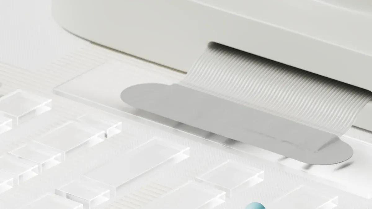
How to Achieve Better Flow with Gate and Runner Design Optimization


You can get better results in injection molding by working on gate and runner design optimization. This helps you control how the material moves into the mold. It also makes the part quality better. Picking the right gate spot changes how the mold fills and lowers defects. You need to think about the part shape and how the material flows to make good choices. Simulation tools and design books give you helpful rules for good gate and runner design optimization. The table below lists important things that affect your injection molding success:
Aspect | Description |
|---|---|
Gating Point | Picking the best gate spot changes how the mold fills and lowers defects. |
Filling Patterns | Checking how the design changes the way material moves during injection to lower weld lines. |
Sensor Monitoring | Using pressure and temperature sensors helps control and improve the injection process. |
Defect Minimization | All these changes help lower defects and make the part quality better. |
Why Gate and Runner Design Matters
Impact on Material Flow and Part Quality
You play a key role in shaping the quality of every molded part through your injection molding gate design choices. The gate controls how the molten plastic enters the mold. When you select the right gate type and location, you help the material flow evenly. This step reduces the risk of defects and improves the quality of plastic parts. Different gates, like direct gates or edge gates, change how fast the mold fills and how the material spreads. If you place the gate in the best spot, you get uniform material flow. This leads to better quality and fewer defects.
Runner sizing also matters. If you size and balance runners correctly, you prevent flow imbalances. This step ensures each cavity fills at the same rate. You get consistent quality across all parts. Good injection molding gate design helps you avoid weak spots and keeps the mechanical properties strong. You can see the results in the quality of plastic parts you produce.
Tip: Always review your gate and runner layout before starting production. Small changes can make a big difference in quality.
Common Flow Defects in Injection Mold Design
You may notice several defects if you overlook proper injection molding gate design. Some common defects include:
Short shots: The mold does not fill completely.
Weld lines: Two flow fronts meet and create a weak line.
Air traps: Air gets stuck and causes bubbles or voids.
Burn marks: Trapped air or fast flow causes discoloration.
Warping: Uneven cooling leads to bent or twisted parts.
You can reduce these defects by focusing on gate placement and runner balance. When you improve your injection molding gate design, you lower the chance of defects and boost part quality. Always check for these issues during your design review. Your attention to detail will help you deliver high-quality parts every time.
Key Factors in Gate and Runner Design Optimization
Gate Types and Placement
You have to make smart choices when picking a gate. The gate changes how the material goes into the mold. It also affects how well the part forms. Look at the shape of your part before you pick a gate. Some gates are tab, hot tip, and pin gates. Each one works best for certain shapes and sizes.
Put the gate where the part is thickest. This helps fill the mold and stops short shots.
Pick the right gate for your material and part size. Hot tip gates are good for making many small parts.
Make sure the gate size fits your part. The size changes how the plastic moves. Change the size if your part shape needs it.
Test your gate design with a computer or by making samples. This helps you see if your design works.
Tips for picking gate spots:
Place gates so the mold fills evenly and weld lines are fewer.
Pick hot runner or cold runner systems based on how many parts you need.
The gate changes how the material moves in the mold. Good gate spots give a smooth finish and fewer weld lines. You get better parts if you follow these tips for picking gate spots.
Runner Sizing and Layout
Runner size and layout are important for filling the mold. You want every cavity to fill the same way. If you design the runner system well, you stop problems like jetting and sink marks.
Make the runner about 1mm bigger than the thickest part. This helps the material fill smoothly.
Use round or trapezoid runners for better flow.
Pick the gating system based on how much material you use, how many cavities you have, and your part shape. This stops filling problems.
Put the gate at the thickest wall to stop sink marks.
In hot runner systems, keep the shear rate steady and watch the heat. This keeps the temperature even.
You need to balance runners in molds with many cavities. Balanced runners help each cavity fill at the same time. You get parts that are the same size and have fewer problems. Runner design changes pressure and flow, so layout matters a lot.
Note: Check your runner design before you start making parts. Small changes in runner size or shape can help filling and lower defects.
Material and Geometry Considerations
Material and part shape change how you design gates and runners. You must match your design to the material and the part shape. The gate and runner choices show up in the final part.
Key Factor | Description |
|---|---|
Gate Types and Placement | The gate type changes how the material moves and the stress. Picking the right gate stops problems. |
The runner system changes how the material moves and the pressure. Cold and hot runners have different good points. | |
Balancing Runners | Balanced runners keep the flow even in molds with many cavities. You stop problems and keep part size the same. |
You can use ribs instead of thick walls to help the material move. Ribs guide the material and help it flow better. Thick walls can cause voids and sink marks, but ribs fix these problems.
Advantage | Description |
|---|---|
Stress Distribution | Ribs spread out stress and make weak spots less likely. |
Void Formation | Ribs lower the chance of voids compared to thick walls. |
Sink Marks | Ribs help stop sink marks and make the surface look nicer. |
You get better filling and parts by thinking about material and shape. You make better gate and runner choices when you match your design to the material and part shape.
Tip: Always check the material sheets and part drawings before you design gates and runners. This helps you avoid mistakes and get the best results.
You control how the mold fills by picking the right gate, gate spot, runner size, and part shape. You see the effect of gate and runner design in every part you make. Use these tips for picking gate spots and runner design to get better filling and better parts.
Gate and Runner Design Optimization Steps
Evaluating Existing Injection Mold Design
First, look at your current injection mold design. Check where the gate is and how the runner is set up. Ask if the gate is at the thickest part. Look for weld lines or short shots in the mold. See if the runner size fits the part size. Notice if the material fills all cavities the same way.
Here is an easy guide to help you optimize your injection molding gate and runner design:
Look at the part drawing and material sheet.
Check if the gate is at the thickest wall.
Look at the runner layout. Make sure all cavities fill evenly.
Search for defects like warping, air traps, or burn marks.
Ask if the gate type matches the part shape and material.
Tip: Use a checklist so you do not forget any important steps when you work on design optimization.
Using Simulation Tools for Optimization
Simulation software lets you test your gate and runner design before making the mold. It helps you see how the material moves inside the mold. You can find problems early and fix them.
Autodesk Moldflow lets you control pressures and flow rates. FLEXflow technology helps you see how valve nozzles open and close. This shows you how pressure builds up in the mold and how much clamping force you need. Moldflow’s filling analysis tells you the best time and place to use valve pins. You can make mold start-up easier and avoid mistakes.
You run tests in the simulation to see if the gate spot causes weld lines or short shots. Change the runner size and layout in the simulation to get even filling. Use simulation to find the best gate for your part and material.
Note: Simulation tools help you test many designs fast. You save time and money by finding the best gate and runner setup before you start making parts.
Collaborating with Toolmakers and Using Design Handbooks
Work with toolmakers to make your gate and runner design better. Share your ideas and get advice from experts. Use simulation tools like Moldex3D with Siemens NX to find defects early. You can see the injection process and make better choices. Real-time feedback helps you try different gate and runner setups. You make fewer changes and get a better product.
Talk with molders and toolmakers to fix hard design problems.
Get tips on gate control and keeping temperature steady for tricky materials.
Work as a team to make the manufacturing process stable.
Learn from experts and get better at design optimization.
Use design handbooks for helpful rules. Handbooks tell you about gate types, runner sizes, and layouts. Follow these rules to avoid mistakes. Check the handbook when you work with a new part or material.
Tip: You get the best results when you use simulation, expert advice, and handbook rules together. You learn how to make the best gate and runner design for every project.
You make your gate and runner design better by following these steps. Use simulation to test your ideas. Work with toolmakers for expert help. Use handbooks for proven rules. You learn how to make the best injection molding gate and get better parts every time.
Avoiding Common Gate and Runner Design Mistakes
Incorrect Gate or Runner Sizing
You need to pay close attention to the size of your gate and runner. If you make the gate or runner too small, you can block the flow of material. If you make them too large, you waste material and may cause flash. Both mistakes can lead to problems like short shots or restricted flow. These issues show how improper molding gate cause injection defects.
Here is a table that shows what can happen if you do not size your gate and runner correctly:
Defect Type | Description |
|---|---|
Short Shots | The mold does not fill all the way because the material cannot flow enough. |
Flash | Extra material leaks out when the gate or runner is too big. |
Restricted Flow | The wrong gate size stops the material from moving smoothly. |
You should make the runner about 1mm larger than the thickest part of your molded part. Use round or trapezoidal runners for better flow. Always check the cross-section and shape before you start production.
Tip: Review your gate and runner sizing during every design review. Small changes can prevent big problems.
Poor Gate Placement Choices
Where you put the gate matters a lot. If you choose the wrong spot, you can create weld lines, weak spots, or uneven filling. Improper molding gate cause injection defects like these, and you may see poor mechanical properties in your parts.
Place the gate at the thickest wall of your part.
Avoid putting the gate in thin or narrow areas.
Try to pour from the center to keep flow lengths equal.
Studies show that the distance from the gate changes the strength of your part. If you do not optimize the gate location, you can get parts with different strengths in different places. Poor gate placement also increases the chance of weld lines and other defects.
Aspect | Description |
|---|---|
Gate Location | Affects how the material flows and where defects may form. |
Mechanical Properties | Parts closer to the gate may be stronger than those farther away. |
Note: Always check for injection molding gate balance. Balanced gates help every cavity fill at the same time and reduce defects.
Overlooking Material-Specific Needs
Every material acts differently in the mold. You must match your gate and runner design to the material you use. If you ignore this, you can get defects or poor part quality.
Follow these best practices:
Place the gate at the thickest part of your product.
Pour from the center when possible for even flow.
Balance the gate and runner system for multi-cavity molds.
If you do not consider the material, improper molding gate cause injection defects that are hard to fix later. Always check the material sheet and adjust your gate and runner design for each new project.
Remember: Injection molding gate balance is key for high-quality parts, especially when you use different materials.
You get better results when you pay attention to each gate. Look at where the gate is, what type it is, and its size for every job. Try out gate designs with simulation tools before you start making parts. Ask experts for help to put the gate in the best spot and stop problems.
Always see if the gate is at the thickest part of your part.
Pick the right gate for your material and the shape of your part.
Change the gate system to make less waste and get better parts.
Simulation lets you safely try gate ideas and show your team what you find.
Aspect | Initial Design | Optimized Design |
|---|---|---|
Runner and gate weight | 100% | 56% |
Quality | Standard | Improved |
You make stronger parts and use fewer resources when you focus on each gate. Check your gate setup now and learn from others to get even better results.
FAQ
What is a gate in injection molding?
A gate is the small opening where molten plastic enters the mold cavity. You control the flow of material with the gate. The gate affects how the part fills and cools. You choose the gate type based on your part’s needs.
How do you pick the best gate location?
You should place the gate at the thickest part of your part. This helps the material flow smoothly. You avoid short shots and get better part strength. Always check your part drawing before you decide on the gate location.
Why does gate size matter?
Gate size changes how fast the material enters the mold. If the gate is too small, you may get short shots. If the gate is too big, you waste material. You need to match the gate size to your part and material.
Can you use more than one gate?
Yes, you can use more than one gate for large or complex parts. Multiple gates help fill the mold evenly. You must balance the gates to avoid weld lines and uneven filling. Always test your design with simulation tools.
How do you know if your gate design works?
You can use simulation software to test your gate design. The software shows how the material flows through the gate. You look for defects like weld lines or air traps. You can also make sample parts to check the gate performance.
See Also
Essential Strategies for Enhancing Manufacturing Route Cards
Achieving Net Shape: The Process in Die Casting
Key Safety Guidelines for High-Speed Cutting Operations
Comprehensive Guide to CAD Design for Die Casting
The Significance of One Piece Flow in Production
About Hunan Puka

Established in 2016 and based in Hunan, China, with a liaison point in Berlin, we are a Tier 2 supplier for the automobile industry. We specialize in the production of customized aluminum die-casting parts designed for machines with a closing force ranging from 280 to 1250 tons, with subsequent manufacturing process CNC machining and surface treatment. Our commitment to quality is reflected in our accredited quality management system, certified by ISO9001:2015 and IATF16949:2016 standards.