Step-by-Step Guide to Die Casting CAD Design

Die casting CAD tools have revolutionized the way you approach mold design. These tools automate repetitive tasks, allowing you to focus on refining complex aspects of the process. By minimizing errors and reducing design time, CAD tools ensure high-precision molds that enhance product quality and lower production costs. Outsourcing CAD services can further optimize your workflow, providing access to specialized expertise and significant cost savings.
To create effective die casting molds, you must follow a structured process. This includes defining design requirements, developing 2D and 3D models, simulating the design, and optimizing it for manufacturability. Each step ensures that your molds meet production standards and deliver superior results.
Understanding Die Casting and CAD Tools
Basics of Die Casting
Overview of the die casting process
The die casting process is a highly efficient manufacturing method used to produce complex metal parts with precision. It involves several key steps:
Heat aluminum alloy ingots until they melt.
Clean and lubricate the two mold halves before closing them.
Clamp the steel or aluminum molds together using a die-casting machine.
Inject molten aluminum into the mold cavity under high pressure.
Allow the casting to cool and solidify.
Separate the mold halves and eject the casting.
Perform secondary operations like sawing, cutting, or surface treatment to remove excess material.
This process ensures high-quality, uniform parts suitable for mass production.
Role of die casting molds in manufacturing
Die casting molds play a critical role in the efficiency and quality of the manufacturing process.
They reduce material waste and scrap, lowering material costs.
Their high thermal conductivity allows faster heating and cooling, cutting energy expenses.
A well-designed mold ensures consistent, defect-free castings, enhancing quality assurance.
Faster cooling times enabled by precise mold design reduce cycle times, boosting production efficiency.
By optimizing the die casting mold making process, you can achieve significant cost savings and improved output.
Importance of CAD Tools in Die Casting Die Design
Benefits of using CAD tools for designing die casting molds
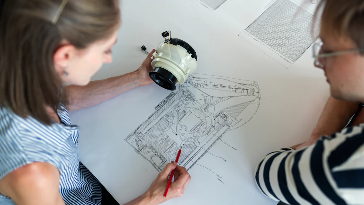
CAD tools have transformed die casting mold design by streamlining the process and improving accuracy. These tools allow you to visualize and refine designs in both two-dimensional and three-dimensional software. They also enable you to simulate the die casting process, identifying potential defects before production begins. This reduces errors, shortens development time, and ensures compliance with manufacturing standards.
Additionally, CAD tools enhance collaboration by allowing you to share designs with team members for feedback. They also support parametric modeling, which provides flexibility to make quick adjustments during the design phase.
Popular CAD software for die casting CAD design
Several CAD tools are widely used in the die casting industry for their advanced features and reliability. These include:
AutoCAD
SolidWorks
Mechanical Desktop (MDT)
Unigraphics
ProE
IDEAS
CATIA
Each of these tools offers unique capabilities, making them indispensable for creating precise and efficient die casting molds. Selecting the right software depends on your specific project requirements and expertise.
Step-by-Step Process for Designing Die Casting Dies
Define Design Requirements
Specify part design and casting requirements.
Before starting the die casting mold design, you must clearly define the part's specifications and casting requirements. This includes selecting appropriate mold materials and thermal treatments to ensure durability. The mold must have sufficient strength to withstand clamping and expansion forces during the die-casting process. Standardized components enhance cost-effectiveness and interchangeability.
You should also calculate the projected area and injection pressure to match the mold with the right machine. Cooling systems play a vital role in managing heat dissipation, ensuring consistent quality. Additionally, consider parting line positioning to minimize flash and simplify part removal. Draft angles in the mold cavity walls facilitate easy ejection, while efficient runner systems and venting channels prevent defects like air pockets.
Identify material and production constraints.
Material behavior and production constraints significantly influence the design. Complex parts, tight tolerances, and high production volumes require meticulous planning. A well-designed mold can improve efficiency by reducing cycle times and enabling faster cooling. This ensures the mass production of high-quality parts within shorter timeframes.
Create Initial 2D/3D Models
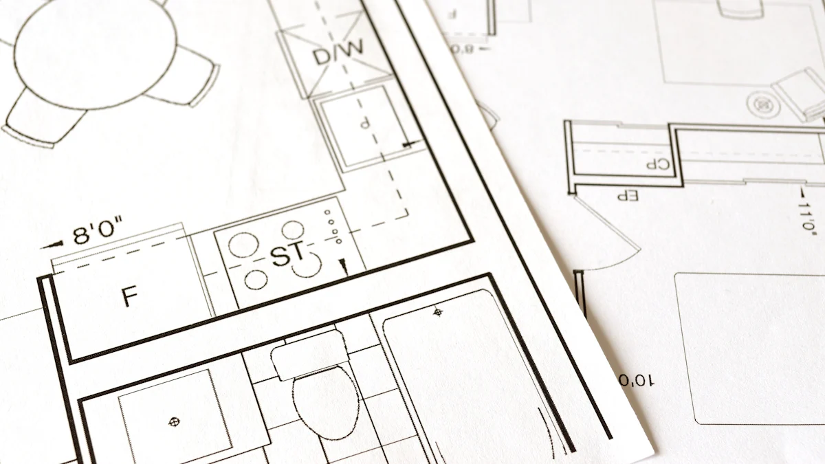
Develop a 2D layout of the die casting mold.
Start by creating a 2D layout to outline the mold's basic structure. This step helps you determine critical features like cavity placement, runner systems, and cooling channels. The layout ensures that the mold's design aligns with the part's geometry and production requirements.
Transition to 3D modeling for detailed die casting die design.
Once the 2D layout is complete, transition to three-dimensional software for detailed modeling. This step allows you to refine internal geometries, such as draft angles and undercuts, ensuring they meet part specifications. Advanced CAD tools enable you to analyze the projection area and cavity volume, ensuring uniform filling and solidification.
Simulate and Analyze the Design
Use CAD simulation tools to test the design.
Simulation is a critical step in the die casting mold making process. Use advanced CAD tools to conduct virtual tests, assessing parameters like material flow and cooling rates. Simulations help you identify potential issues, such as uneven filling or thermal imbalances, before production begins.
Identify and address potential defects or inefficiencies.
Common defects like flashing, porosity, and shrinkage can compromise the mold's performance. Simulations allow you to pinpoint these issues and make necessary adjustments. For example, optimizing venting channels can prevent air pockets, while refining cooling systems ensures consistent solidification. Addressing these inefficiencies early reduces production delays and enhances mold quality.
Optimize the Design for Manufacturability
Adjust the design for production efficiency and quality.
To optimize your die casting mold for manufacturability, focus on refining its features to enhance production efficiency and ensure high-quality output. Start by adjusting the size and shape of injection channels to meet fluid dynamics requirements. This prevents defects like uneven filling or porosity. Incorporate overflows to collect initial metal shots, which helps manage temperature variations and reduces casting defects.
Choose the appropriate die closing method based on the complexity of the part. This facilitates easier ejection and minimizes wear on the mold. Balance the number of cavities in the mold to optimize production efficiency while managing cooling and material flow challenges. Accurate projection area analysis ensures uniform filling and solidification, reducing the risk of defects.
Use advanced CAD tools to simulate and refine the mold’s internal geometry. This ensures the volume and shape match the desired specifications, providing precise control over material flow. By implementing these strategies, you can streamline the die casting mold making process and achieve consistent results.
Ensure compliance with manufacturing standards.
Your die casting mold design must comply with industry standards to ensure reliability and safety. Verify that all dimensions, tolerances, and material specifications meet the required guidelines. Use simulation tools to test the mold under various conditions, ensuring it performs as expected during the die casting process. Compliance not only guarantees quality but also minimizes the risk of production delays or costly redesigns.
Finalize and Validate the Design
Conduct final reviews and validations.
Before moving to production, conduct a thorough review of your die casting mold design. Identify specific features, dimensions, or complexities that could impact performance. Assess the projection area and cavity volume to ensure uniform filling and solidification. Use CAD and simulation tools to refine the design further, addressing any remaining inefficiencies.
Perform a trial casting to verify that the mold produces parts meeting the desired specifications. Analyze the results and make adjustments as needed. This step ensures the mold is optimized for real-world conditions and delivers consistent, high-quality parts.
💡 Tip: Use computer-aided engineering (CAE) software to simulate the mold’s performance during the casting process. This helps identify potential issues before production begins.
Prepare the die casting mold for production.
Once the design is finalized, prepare the mold for production by selecting the appropriate tooling. Use production dies for high-volume manufacturing, unit dies for simpler components, or trim dies to remove excess material after casting. Assemble the mold halves with precision to ensure a tight fit, and integrate a cooling system to manage heat dissipation efficiently.
Test the mold with a trial run to confirm its readiness for full-scale production. Address any final adjustments based on the test results. By following these steps, you can ensure your die casting mold is ready to deliver optimal performance in the manufacturing process.
Best Practices for Using CAD Tools in Die Casting Mold Design
Organize Your Workflow
Use templates and libraries for efficiency.
Templates and libraries streamline the die casting mold design process by providing pre-built components and standardized layouts. You can save time by reusing these resources instead of starting from scratch. Many CAD tools offer libraries with common features like runners, gates, and cooling channels. Using these elements ensures consistency and reduces the likelihood of errors. Templates also help you maintain uniformity across multiple projects, improving overall efficiency.
Maintain a structured file management system.
A well-organized file management system is essential for handling complex die casting mold designs. Create a clear folder structure with descriptive file names to make it easier to locate and update your work. Version control is equally important. Save iterations of your design to track changes and revert to previous versions if needed. This practice minimizes confusion and ensures that your files remain accessible and up-to-date throughout the die casting mold making process.
Leverage Advanced CAD Features
Use parametric modeling for flexibility in die casting CAD design.
Parametric modeling enhances flexibility by maintaining a history of design changes and establishing relationships between components. When you modify one part of the design, related elements automatically update. This feature reduces errors and saves time, especially when working on intricate die casting mold designs. By using parametric modeling, you can quickly adapt to changes in specifications or production requirements without starting over.
Utilize built-in simulation tools for accuracy.
Simulation tools in CAD software allow you to test your die casting mold design virtually. These tools model complex processes like material flow and cooling rates, helping you identify potential issues before production. For example, mold flow simulation predicts how zinc alloy will behave during the die casting process, enabling you to address defects like porosity or surface imperfections. This proactive approach ensures precise dimensions and enhances the reliability of your molds.
Collaborate Effectively
Share designs with team members for feedback.
Sharing your die casting mold designs with team members fosters collaboration and improves the final product. Use the right file format to ensure compatibility and maintain quality. Cloud-based tools simplify file sharing by syncing and storing designs online, making them accessible to all stakeholders. Manage file versions carefully to avoid overwriting important data. Regularly test and review shared files to ensure accuracy and consistency.
Use cloud-based tools for real-time collaboration.
Cloud-based tools enhance teamwork by enabling real-time collaboration on die casting mold designs. These platforms provide instant access to shared resources, allowing team members to work together seamlessly. Features like virtual meetings and live editing make it easier to develop manufacturable casting designs. By leveraging cloud computing, you can improve productivity and ensure that everyone stays aligned throughout the design process.
Common Challenges in Die Casting CAD Design and Solutions
Managing Complex Die Casting Mold Designs
Break the design into smaller, manageable components.
Complex die casting mold designs often present challenges like porosity, flashing, and shrinkage. Tackling these issues becomes easier when you divide the design into smaller, manageable parts. Focus on individual components such as runners, gates, and cooling channels. This approach allows you to address specific issues like material flow or thermal imbalances without overwhelming the entire process. By isolating problem areas, you can refine each section for optimal performance.
Use modular design techniques for efficiency.
Modular design simplifies the creation and maintenance of die casting molds. It enables you to reuse standardized components, reducing costs and saving time. Modular molds also allow for quick adjustments, making it easier to implement product variations. For example, lightweight modular dies consume less energy during preheating and operation, contributing to energy efficiency. This method enhances flexibility and ensures your molds remain adaptable to changing production needs.
Addressing Material and Production Constraints
Select appropriate materials for the die casting mold.
Choosing the right material is critical for ensuring durability and performance. Materials like H13 tool steel offer toughness and resistance to thermal fatigue, making them ideal for high-stress environments. Hot work steel (H11) provides excellent wear resistance at elevated temperatures, while beryllium copper inserts improve heat dissipation and reduce cycle times. Evaluate your production requirements to select materials that balance cost, strength, and thermal properties effectively.
Material Type | Key Properties |
|---|---|
H13 Tool Steel | Toughness, resistance to thermal fatigue, ideal for high temperatures and stress |
Hot Work Steel (H11) | Good wear resistance and toughness at elevated temperatures |
Beryllium Copper Inserts | Improved heat dissipation, enhances cooling rates, reduces cycle times |
Optimize the design for the chosen production method.
Tailoring your die casting mold to the production method ensures efficiency and quality. Co-designing with clients helps align the mold with specific component requirements. Use advanced simulation tools to refine the mold, ensuring uniform cooling and minimizing defects like porosity. Adjust the number of cavities to balance production speed with material flow and cooling challenges. These steps maximize material efficiency and reduce waste during the die casting process.
Ensuring Accuracy and Precision
Double-check dimensions and tolerances in the design.
Precision is essential in die casting mold creation. Double-check all dimensions and tolerances to ensure they meet specifications. Pay close attention to critical features like runners, gates, and cavity volumes. Proper runner system design minimizes defects and ensures consistent material flow. A well-designed mold guarantees uniformity in the final product, reducing variations and defects.
Use automated tools to minimize human error.
Automated tools streamline the design process and reduce the risk of errors. Software like Synera automates routine calculations, speeding up development and improving accuracy. Automated inspection systems identify defects immediately, allowing for quick corrections. These tools enhance the quality of your die casting molds and ensure consistent results throughout the manufacturing process.
FAQ
What is the most important factor in die casting mold design?
The most critical factor is ensuring the mold meets the part's specifications. This includes proper dimensions, tolerances, and material selection. A well-designed mold ensures uniform filling, minimizes defects, and enhances production efficiency.
How do CAD tools improve die casting mold design?
CAD tools streamline the design process by enabling precise modeling, simulation, and analysis. They help you identify potential defects, optimize material flow, and ensure compliance with manufacturing standards. These tools also save time and reduce errors.
Which CAD software is best for die casting mold design?
The best software depends on your project needs. Popular options include SolidWorks for 3D modeling, AutoCAD for 2D layouts, and CATIA for complex designs. Evaluate features like simulation capabilities and user interface to choose the right tool.
How can you avoid defects in die casting molds?
Use CAD simulation tools to test material flow and cooling rates. Optimize venting channels to prevent air pockets. Adjust runner systems to ensure uniform filling. Regularly review and refine your design to address potential issues early.
Why is simulation important in die casting CAD design?
Simulation allows you to test your mold design virtually. It helps you predict material behavior, cooling rates, and potential defects. By addressing these issues before production, you save time, reduce costs, and ensure high-quality results.
See Also
Finding The Ideal Closing Force For Die Casting Products
Seven Essential Steps To Collaborate With A Diecast Factory
Understanding Functional Testing In CNC And Die Casting
Exploring Anodizing And Its Application In Die Casting
A Supplier's Guide To CBAM And Sustainable Casting Practices
About Hunan Puka

Established in 2016 and based in Hunan, China, with a liaison point in Berlin, we are a Tier 2 supplier for the automobile industry. We specialize in the production of customized aluminum die-casting parts designed for machines with a closing force ranging from 280 to 800 tons, with subsequent manufacturing process CNC machining and surface treatment. Our commitment to quality is reflected in our accredited quality management system, certified by ISO9001:2015 and IATF16949:2016 standards.